

FCC FLUE-GAS EQUIPMENT
Reduce flow resistance in the water seal tank and its connected pipework
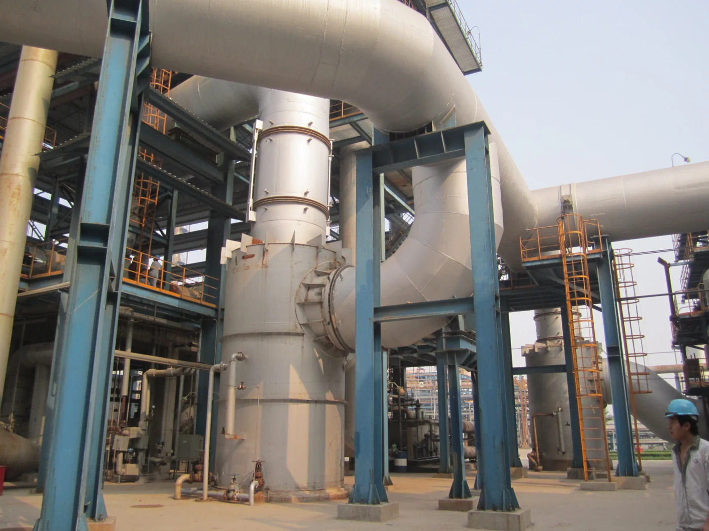
Ruichang’s low-pressure-drop water seal tanks are designed for FCC flue-gas systems. The internal geometry is designed to reduce resistance as gas changes direction through the vessel. For a retrofit, the tank must be assessed alongside the inlet and outlet ducts, available space and required sealing function.
Discuss a water seal tankWhy the flow path matters
A water seal tank can add substantial resistance to the flue-gas path. In an FCC power-recovery system, higher downstream resistance can increase the backpressure on the expander. The effect on recovered power depends on the operating conditions of the whole system.
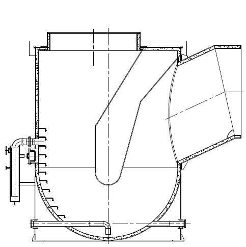
Tank geometry
The technical study examines guide-cone, float-drum and streamlined arrangements. These arrangements guide gas through the vessel in different ways. Selection also depends on the sealing arrangement and access for maintenance.
Connected ducts
Elbows, transitions and adjacent equipment influence the total pressure loss. Redesigning the tank alone may leave a restriction elsewhere in the system.
Pressure-drop results from the technical study
Ruichang’s development material reports the following comparisons. These are results from the documented study and its example systems; they are not a standard performance range for every tank.
| Study item | Reported result |
|---|---|
| New tank designs compared with the original design | 50–80% lower pressure drop in the reported development comparison. |
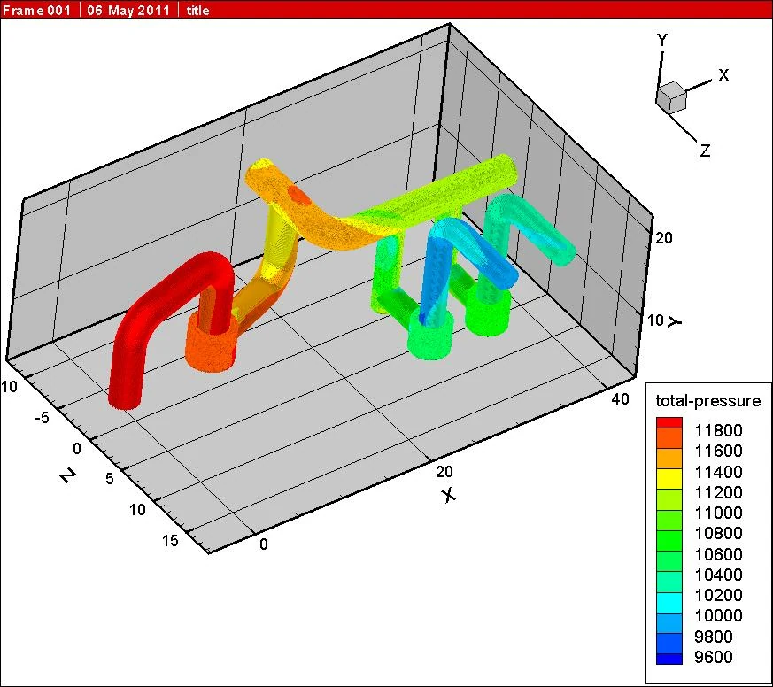
| Original example pipe system | Approximately 5,000 Pa total pressure loss; main-line gas velocity reported as 32 m/s. |
| Optimized example pipe system, including three water seal tanks | Approximately 2,300 Pa total pressure loss. |
Source: Ruichang, “New Low-Pressure-Drop Water Seal Tank” technical material. The pipe-system figures describe the complete example system, not the pressure drop across one tank. Agree the test conditions and acceptance criteria for each project.
Define the comparison before specifying the target
The study defines pressure loss using the difference between area-averaged total pressure at the inlet and outlet. A reading from one local pressure tap may not represent that average. An enquiry should identify whether its pressure figures are static or total pressure, where they were taken and the flow conditions at the time.
Compare the existing arrangement and proposed replacement at the same operating conditions. Any energy-saving estimate also needs the expander data and actual operating hours.
Data needed for a replacement or new installation
| Design input | Details to provide |
|---|---|
| Flue gas | Composition, normal and maximum flow, temperature, pressure and solids loading where known. |
| Pressure-loss requirement | Existing measurements, measurement locations, operating case and allowable loss across the proposed scope. |
| Mechanical arrangement | Tank and duct drawings, connection sizes, elevations, support locations and access restrictions. |
| Sealing and utilities | Required sealing duty and the available water, drain and instrumentation connections. |
| Retrofit scope | Equipment retained, proposed duct changes, shutdown window and inspection requirements. |
For a broader review, see the FCC equipment range and low-pressure-drop auxiliary chamber.
Review your tank and ductwork together
Send the existing arrangement and the operating data you have. Mark estimated values in the enquiry so they can be checked before a performance target is agreed.
Send tank data
